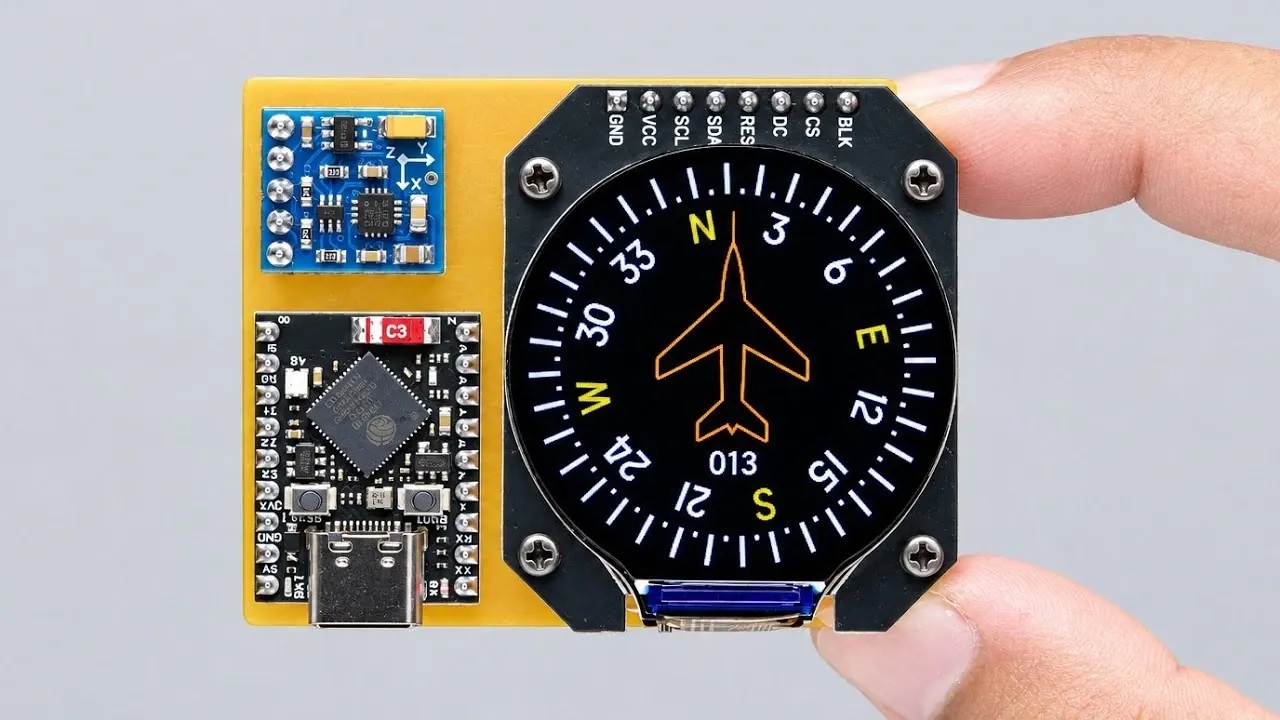
Creating a magnetic heading indicator with an ESP32 microcontroller and a round display is a project that combines technical precision with creative design. LazyDays Creation demonstrates how to integrate key components like a three-axis magnetometer sensor, a rechargeable lithium battery and a custom adapter board to build a functional digital compass. The process involves assembling hardware, such as soldering connector pins and securely mounting the display, followed by developing software to process sensor data and display real-time heading information. This project not only emphasizes the importance of careful calibration to ensure accuracy but also showcases how thoughtful component selection can enhance both performance and usability.
Dive into this breakdown to explore the essential steps for assembling and programming your own magnetic heading indicator. You’ll gain insight into designing a user-friendly interface using SquareLine Studio, optimizing code for responsive performance and calibrating the magnetometer sensor to eliminate environmental inaccuracies. Whether you’re interested in the technical assembly process or the software development phase, this guide provides a clear path to creating a reliable and visually appealing digital compass.
TL;DR Key Takeaways :
- The project involves creating a portable digital compass using an ESP32 microcontroller, a three-axis magnetometer sensor, a round color display and a rechargeable lithium battery, combining hardware assembly, software development and sensor calibration.
- Key components include the ESP32 for processing and connectivity, the magnetometer sensor for detecting magnetic fields, a circular display for visualizing readings and a custom adapter board for streamlined wiring and durability.
- The assembly process emphasizes precision, including soldering, integrating the display and designing a custom adapter board to ensure reliable functionality and ease of use.
- Software development focuses on creating an intuitive user interface using SquareLine Studio and programming the ESP32 to process sensor data and display real-time heading information efficiently.
- Proper calibration of the magnetometer sensor is essential to ensure accuracy, requiring initial and periodic recalibration to account for environmental factors and maintain reliable performance.
Essential Components for the Digital Compass
Choosing the right components is critical to the success of your magnetic heading indicator. Each part contributes to the device’s functionality, performance and usability. Below are the key components required for this project:
- ESP32 Microcontroller: The ESP32 acts as the central processing unit, offering built-in Wi-Fi, Bluetooth and a battery management system. Its versatility and power efficiency make it ideal for portable applications.
- Three-Axis Magnetometer Sensor: This sensor is the core of the compass, detecting magnetic fields and determining the heading direction with precision.
- Round Color Display: A modern, circular display provides a user-friendly interface for visualizing compass readings, enhancing both the aesthetics and functionality of the device.
- Rechargeable Lithium Battery: A portable power source ensures the device operates independently without requiring a constant external power connection.
- Custom Adapter Board: This simplifies the wiring process by connecting the ESP32, magnetometer sensor and display, improving both durability and ease of assembly.
Each of these components plays a vital role in making sure the device operates seamlessly and delivers accurate results.
Step-by-Step Assembly Process
The assembly process is a crucial phase where precision and attention to detail are essential. Properly connecting and securing the components ensures the device functions as intended. Follow these steps to assemble your digital compass:
- Soldering: Begin by soldering connector pins onto the ESP32 board. This step establishes secure electrical connections between the microcontroller and other components, making sure reliable communication.
- Display Integration: Test the round color display to confirm its functionality. Once verified, connect it to the ESP32 and securely mount it to the housing to prevent movement or disconnections during use.
- Custom Adapter Board: Design and assemble a custom adapter board to streamline the wiring process. This board simplifies connections between the ESP32, magnetometer sensor and display, reducing clutter and enhancing the device’s durability.
Once the hardware is fully assembled, the next step is to bring the device to life through software development.

Check out more relevant guides from our extensive collection on ESP32 that you might find useful.
- $5 ESP32-S3 Super Mini Packs Wi-Fi and Bluetooth
- How an $8 ESP32 S3 Microcontroller Runs a 28.9M Parameter Local LLM
- $4 ESP32 Module Brings Wi-Fi and Bluetooth to IoT Projects
- ESP32-S3 Super Mini Brings 240 MHz Dual-Core Power For $4
- ESP32 S31 Devkit Hands-on: 320 MHz RISC-V Chip Adds Wi-Fi 6
- $4 ESP32-S3 Super Mini Packs a 0.96-Inch IPS TFT Screen
- Build a DIY Open source Flipper Zero Using a ESP32-DIV
- WaveShare ESP32-C5 Offers 32MB Flash and Sensors For $20
- $9 CYD ESP32 Module Includes a 2.88-Inch LCD Screen
- ESP32-S3 Super Mini Costs $5 and Packs Wi-Fi and Bluetooth
Designing and Developing the Software
The software is the backbone of your magnetic heading indicator, allowing it to process sensor data and display accurate readings. A well-designed program ensures smooth operation and an intuitive user experience. Here’s how to approach the software development phase:
- User Interface Design: Use SquareLine Studio to create a professional and visually appealing interface. This tool allows you to customize the layout, making sure the display is both functional and easy to read. Export the necessary files for integration with the ESP32.
- Programming the ESP32: Write and upload the code to process data from the magnetometer sensor. The program should calculate the heading direction and display the information in real-time on the screen. Focus on optimizing the code for efficiency and responsiveness.
By combining a polished user interface with efficient programming, your digital compass will deliver accurate and reliable performance.
Calibrating the Magnetometer Sensor
Calibration is a critical step to ensure the accuracy of your magnetic heading indicator. Environmental factors, such as nearby metallic objects or magnetic interference, can affect the sensor’s performance. Proper calibration eliminates these inaccuracies and ensures reliable readings. Follow these calibration steps:
- Initial Calibration: Rotate the device in all directions to map the surrounding magnetic field. This process helps eliminate offsets and ensures the sensor provides precise heading information.
- Recalibration: If the device is moved to a new environment or the sensor’s position is altered, recalibration may be necessary. Regular recalibration ensures consistent accuracy, regardless of changes in the surroundings.
Accurate calibration is essential for maintaining the reliability of your compass in various conditions.
The Final Product
By combining the ESP32 microcontroller, three-axis magnetometer sensor, round color display and rechargeable lithium battery, you can create a portable and fully functional digital compass. The inclusion of a custom adapter board simplifies the wiring process, while the user interface designed in SquareLine Studio enhances usability and visual appeal. Once calibrated, the device provides precise magnetic heading information, making it a valuable tool for navigation, education, or personal projects.
This project highlights the potential of microcontroller-based designs in creating innovative and portable electronic devices. Whether you’re an experienced developer or a hobbyist exploring the intersection of hardware and software, building a magnetic heading indicator is an excellent way to enhance your skills and create a practical, real-world application.
Media Credit: LazyDays Creation
Disclosure: Some of our articles include affiliate links. If you buy something through one of these links, Geeky Gadgets may earn an affiliate commission. Learn about our Disclosure Policy.
