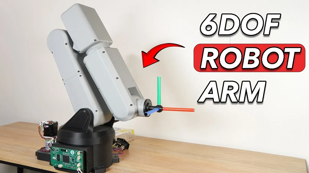
Steve & Stanley spent two years creating a six degrees of freedom (6-DOF) robotic arm from scratch, combining mechanical engineering, electronics and software into a unified system. Their process involved over 5,000 lines of custom code and several hardware revisions. One notable feature of their design was the direct motor mounting on Joint 3, which minimized backlash and improved stability. Other key elements, such as internal cable routing and a tapered roller bearing at the base, addressed challenges like load distribution and precise movement.
Explore the mechanical design process, including strategies for belt tensioning and making sure structural durability. Gain insight into how a custom PCB and CAN bus architecture streamlined the electronics while improving reliability. Learn about the custom firmware that enabled advanced motion control and real-time debugging, providing a detailed view of the software development involved.
Mechanical Design: Challenges & Innovations
TL;DR Key Takeaways :
- The 6-DOF robotic arm was developed over two years, combining mechanical engineering, electronics and software, with over 5,000 lines of custom code and multiple hardware iterations.
- Key mechanical upgrades included direct motor mounting, enhanced base stability, refined belt tensioning and internal cable routing, improving torque, precision and durability.
- The electronics system was streamlined with a custom PCB, a CAN bus architecture reducing wiring complexity and advanced microcontrollers for improved performance and scalability.
- Custom firmware enabled precise motion control, inverse kinematics and real-time communication, with AI tools optimizing code for efficiency and reliability.
- Extensive testing and iterative improvements addressed issues in PCB design, firmware, assembly and power distribution, making sure a robust and reliable robotic system with future enhancement potential.
The mechanical design of the robot arm presented numerous challenges, particularly in achieving the necessary torque, precision and structural durability. Early prototypes revealed significant limitations, such as inadequate strength in 3D-printed shafts and timing belts, prompting a series of critical design improvements:
- Direct Motor Mounting: A redesign of Joint 3 incorporated direct motor mounting, which effectively reduced backlash and enhanced overall stability.
- Enhanced Base Stability: The addition of a tapered roller bearing to the base allowed the arm to support heavier loads while maintaining stability.
- Refined Belt Tensioning: Adjustable tensioning mechanisms were introduced to ensure consistent performance and reduce wear over time.
- Internal Cable Routing: Wires were routed internally, improving the arm’s aesthetics and minimizing the risk of accidental damage during operation.
These mechanical upgrades were pivotal in creating a robust and reliable robotic arm capable of executing precise movements under varying load conditions. Each improvement addressed specific performance bottlenecks, making sure the arm met its design objectives.
Electronics Development : Streamlining Complexity
The electronics system underwent significant refinement to balance performance, cost and complexity. Initially, the project utilized a TNC 4.1 microcontroller, but this was later replaced with an ESP32, which offered superior performance at a lower cost. This transition necessitated the development of a custom PCB tailored to the arm’s unique requirements.
To simplify the wiring and improve system reliability, a CAN bus architecture was implemented. This reduced the number of wires from 32 to just 4, allowing a distributed control system with the following key components:
- Main Controller: The STM32H7R7 microcontroller was selected for its high processing speed, integrated floating-point unit and support for an LCD display.
- Stepper Motor Drivers: Custom drivers were developed using STM32G431 microcontrollers and TMC chips, making sure precise control of Nema 17 and Nema 23 motors.
These advancements streamlined the electronics system, reducing complexity while enhancing reliability and scalability. The integration of a CAN bus architecture also facilitated easier debugging and future upgrades.

Find more information on robot arm by browsing our extensive range of articles, guides and tutorials.
- Palm-Sized 6-Axis Robotic Arm for Microelectronics and Labs
- How to build a Robot Arm using 3D printed Parts and Arduino
- AMBER B1 modular 7-axis robot arm
- ArcDroid CNC desktop plasma cutter from $2,100
- Arduino DIY custom robotic arm
- MeArm Open Source Pocket Robotic Arm (video)
- Mirobot 6-axis mini robot arm
- Build a Mini Robot Arm with Arduino
- Build A Desktop Robot Arm With Arduino.Webp
- AR4-MK3 6DOF axis open source robot arm kit
Firmware Development : Custom Code for Precision
The robot arm’s functionality relied heavily on custom firmware, carefully developed to handle motion control, inverse kinematics and communication protocols. This software was the backbone of the system, allowing precise and responsive operation. Key aspects of the firmware development process included:
- Motion Control Algorithms: Custom algorithms were designed to ensure smooth and accurate movements across all six degrees of freedom.
- Code Optimization: AI tools were utilized to review and refine the code, enhancing its efficiency and reliability.
- Serial Communication Interface: A dedicated interface was created to enable real-time testing, parameter adjustments and debugging of both hardware and software.
The firmware’s tailored design was instrumental in achieving the arm’s high level of precision and responsiveness. Each feature was carefully developed to meet the specific demands of the project, making sure seamless integration with the hardware.
Testing and Iterative Improvements
Extensive testing played a crucial role in identifying areas for improvement, leading to iterative refinements across both hardware and software. These adjustments were essential in transforming the robot arm into a dependable and efficient system. Key improvements included:
- PCB Layout Refinements: Signal integrity issues were resolved by optimizing the PCB design, making sure reliable communication between components.
- Firmware Adjustments: Configurations were fine-tuned to enhance compatibility and performance with the hardware.
- Assembly Corrections: Errors in assembly were identified and corrected, improving the overall reliability of the system.
- Display Optimization: Performance issues with the LCD display were addressed by refining the display driver and communication protocols.
- Sensor Calibration: Proximity sensors were calibrated to improve accuracy and responsiveness during operation.
- Power Distribution Redesign: Limitations in the power supply were resolved to ensure consistent performance under load.
These iterative improvements underscored the importance of thorough testing and continuous refinement in achieving a high-performing robotic system.
Future Enhancements & Opportunities
The foundation of this project offers significant potential for further development and innovation. Several planned enhancements aim to elevate the arm’s performance and expand its capabilities:
- Touchscreen Interface: Integrating a touchscreen to provide a more intuitive and user-friendly control interface.
- Refined Motion Algorithms: Further optimizing motion control algorithms to achieve smoother and more precise movements.
- Magnetic Encoders: Incorporating magnetic encoders to enable closed-loop control, enhancing accuracy and responsiveness.
These advancements could transform the robotic arm into a more versatile tool, suitable for a wide range of applications in fields such as manufacturing, research and education. The project serves as a testament to the power of iterative design and the potential for continuous improvement in robotics.
Media Credit: Steve & Stanley
Disclosure: Some of our articles include affiliate links. If you buy something through one of these links, Geeky Gadgets may earn an affiliate commission. Learn about our Disclosure Policy.